
Year
2026
client
Neurophos Inc.
Category
Introduction
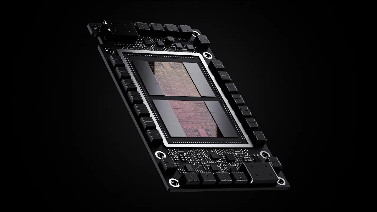
Neurophos is building photonic computing hardware for next-generation AI infrastructure, using light to move and process information in ways traditional electronic systems cannot. The product itself is extremely small and highly technical, which makes it difficult to show through conventional imagery. My work started with the 3D modelling of the hardware and its related components, then moved into CGI stills and animations designed to make the technology easier to read and communicate.
Beyond the final images, this project is about the process of making complexity visible. Each scene opens a small part of the workflow, showing how a technical object was shaped, lit, framed and refined until it became readable as a visual story. Because a picture is worth a thousand words.
Index
Chapter 0 — Visual Mood & Textures Development (Midjourney) Chapter 1 — 3D Assets Development Chapter 2 — Hybrid Lighting Chapter 3 — Making Micro-Hardware Readable Chapter 4 — Visualizing Optical Connections Chapter 5 — From Single Module to System Chapter 6 — Building the Tray System Chapter 7 — Infographic Chapter 8 — Editing (AE + Topaz AI) Chapter 9 — Static Renders
Chapter 0 · Visual Mood & Textures Development (Midjourney)
The visual direction was built around a dark, dramatic environment, where the hardware could emerge through deep shadows and controlled highlights. The goal was to avoid a flat technical render and create a more cinematic image, using contrast as a way to guide attention. The dark scene helped create depth and tension, while the sharp highlights added precision and a more premium deep-tech atmosphere.

The chip itself is a microscopic element, so representing it at this scale required a certain level of interpretation. To make its internal structure visible and readable, especially the metasurface area, I developed a custom chip texture based on multiple technical and visual references. The texture was developed through a combined Midjourney and Adobe Photoshop, using reference material as a starting point to generate and refine a surface language that could suggest density and micro-scale complexity without becoming visually noisy.

Chapter 1 · 3D Assets Development
The 3D asset was developed as a layered structure, allowing each part of the hardware to be controlled independently during rendering. This was especially important for the chip area, where the surface needed to carry both technical detail and strong visual reflections. To achieve this, the chip was built with two overlapping surfaces: _ A base surface dedicated to the custom chip texture _ A second identical surface placed slightly above it with KeyShot’s Thin Film material applied.

Thin Film material creates an iridescent effect similar to a soap bubble, allowing colored reflections to move across the chip without interfering with the underlying texture by controlling refractive index and thickness. The result was a more flexible rendering setup, where the microscopic surface detail and the cinematic reflective behavior could be controlled separately.

Chapter 2 · Hybrid Lighting
Lighting became one of the key tools for controlling hierarchy across the renders. The setup was built as a hybrid system: _ HDRI lighting with soft custom light pins was used to create the overall scene illumination and softly reveal the external PCB details; _ Physical light panels were added to generate stronger, more directional reflections across the chip surfaces. This made it possible to keep the black hardware readable without overexposing the scene, while using colored highlights and controlled specular reflections to constantly pull the focus back to the chip area.


Chapter 3 · Making Micro-Hardware Readable
The first visual challenge was to make the module readable at a very close scale without losing the density of the hardware. The 3D model was built as a layered system: PCB base, interposer frame, chip areas, memory blocks, micro-components, connector details and fine surface patterns. In KeyShot, the lighting had to bring out the geometry without flattening the black materials, so I worked with controlled grazing highlights, low-key illumination and subtle color reflections across the chip surface. The camera angles were chosen to sit between a product render and a technical macro view: close enough to show the microscopic complexity, but wide enough to keep the architecture of the module understandable.
Chapter 4 · Visualizing Optical Connections
One of the main challenges was showing how the optical fibers leave the chip area and connect to the surrounding PCBs without making the scene too crowded. To make this clearer, I developed an animated sectional view using simple cube geometries as subtraction volumes. In KeyShot, these were assigned the special Cutaway material, allowing the model to be sliced directly inside the rendering scene. This made it possible to create photorealistic, non-destructive cross-sections of the assembly without modifying the original CAD model, while keeping the fibers, chip surfaces, and PCB connections visually readable.
Chapter 5 · From Single Module to System
Once the main chip visualization was defined, the next step was to expand the scene beyond a single PCB. These views were built to introduce the idea of multiple hardware modules working together, connected through optical fibers while still keeping the chip as the visual anchor of the composition. The main challenge was balancing scale and complexity: showing a larger system without letting the scene become visually crowded. The camera was kept low and close to the boards, using perspective to suggest depth and repetition, while the lighting remained focused on the chip areas to guide the viewer through the growing architecture of the system.

Chapter 6 · Building the Tray System
The next step was to place the hardware inside a larger tray structure, showing how multiple boards could operate as part of a more complex system. The challenge was to introduce this wider architecture without losing the chip as the main visual focus. The tray was modeled as a layered support platform, with separate functional areas for the PCBs, structural details, connector zones, and fiber routing. An exploded view helped clarify how the system is assembled, while the rendering kept the same dark, controlled visual language used in the previous scenes. In KeyShot, the lighting was used to separate the tray surfaces from the smaller modules, keeping the fibers bright and readable as the visual element that connects the individual boards into a single system.

Chapter 7 · Infographic
To explain the behavior of the metasurface in a more immediate way, I developed a simplified infographic animation based on light and data flow. A red beam was used to represent the incoming stream of information as it passes through the metasurface, while the blue stacked elements show the processed information accumulating on the side of the chip. The goal was to create a clear visual metaphor that could make the interaction between light, surface and data easier to understand. The animation keeps the same dark, cinematic language of the project, using color contrast and controlled motion to separate the input signal from the generated information stack.
Chapter 8 · Editing (AE + Topaz AI)
Each animation was rendered as an image sequence rather than a single video file, giving more control over quality, timing, and post-production. The frames were first assembled in Adobe After Effects, where the individual clips were exported and prepared for enhancement. They were then processed through Topaz Labs Astra, using AI-based upscaling, FPS improvement and motion refinement to increase sharpness and fluidity without changing the original 3D animation. The final video was edited back in After Effects, where adjustment layers were used to fine-tune contrast, highlights, detail, and overall visual consistency across the different scenes.

Chapter 9 · Static Renders
For the static visuals, the images were rendered directly in KeyShot rather than extracted from the animation frames. This allowed each still to be treated as a dedicated final output, with higher sample settings and a print-oriented resolution setup. Since these images could be intended not only for web use but potentially also for printed communication, the renders were prepared at 300 dpi to allow flexibility across different formats. After rendering, the images were post-produced in Adobe Lightroom Classic, where contrast, highlights, color balance, clarity, and fine details were adjusted to create a consistent final look.


Credits & Attribution
All intellectual property related to the technology, hardware architecture and underlying product development belongs exclusively to Neurophos. The 3D models, CGI visuals, renderings and animations presented in this project were developed by Alessandro Pennese for visualization, digital marketing, web, presentation and print communication purposes. Any sharing, publication or redistribution of these contents downloaded from the platform must include proper attribution to Neurophos for the technology and to Alessandro Pennese for the CGI visualization work, unless otherwise agreed. The creation, reproduction, modification or distribution of derivative works based on these contents is not permitted without prior written authorization by Neurophos.
